|
Last updated :July 7th 2009 If you wish to add any entries to this FAQ, or amend existing entries, please send me an email with details of changes. All contributions welcome. |
|
|
|
New
buyers guide What are the performance figures for the 650 (99-02)? What are the performance figures for the 650 03- What
are the specifications for the 1000? |
| Thanks to all the contributors who took the time and trouble to send their 'how to' information into the web.... |
| How do I: install new suspension dog bones to lower the suspension |
| Where can I: learn more about Carb Icing |
| Can I: buy a SV650 repair manual? |
| Where can I get a copy of Suzukis parts fiche |
| Want to: find out more about Renegade Exhausts in the UK? |
| How to: deal with water in the fuel |
| How to: change fork oil |
| How to: shim carb needles & images on how to shim carb needles |
| How to: make balancing the carbs easier |
| How to: replace brake pads |
| How to: build a SV650R |
| How to: fit an undertray |
| How to: fit a Givi rack |
| How to: fit a high level Micron exhaust system |
| How to: fit soft panniers |
| How to: fit a Scotoiler (non-touring kit) |
| How to: additional instructions on fitting a Scottoiler kit (non-touring) |
| How to: fit a Scotoiler (Touring Kit) plus additional information here |
| How to: fit a Fenda Extenda |
| How to: information about Vance & Hines S4 full system |
|
How to: carb
needle shimming / rejetting / adjusting air/fuel mixture / removing air
filter snorkel (the air filter
snorkel removal will *not*
increase power) |
| How to: How to - un-seize the front brake calipers |
| How to: How to - The lazy way of front fork adjustment |
| How to: install a Targa Fairing |
| How to: install heated grips |
| How to: fit an under tray |
| How to: get replacement keys |
| How to: disengage the ignition retarder. |
| What are the correct tyre pressures for Avon tyres (av35/36) |
| What do I need to know about the 2000 model recall |
| How to Fit a Red Racing carbon fairing |
| How do I remove seized rear brake pins - by Ian Vine |
| How to Fit FIAMM horns - by Mark Horridge |
| How to remove and check cam chain tensioners |
| What is the paint code for my bike |
| How to install the offset ignition advance key Big 1.2Mb |
| Can I fit a GSXR frontend to my SV? |
| How to fill in the grabrail gaps, cheaply from Stu Kennedy Big 1.35Mb |
| What exhaust should I buy from Phillip Poulton (excel version) |
| How to make a fender eliminator for the '03 SV by Mitch |
| How to Fit an adjustable clutch lever to the SV650 |
| How to adjust the throttle position sensor on an SK3 SV |
| How to do the TRE mod on an SK3 and above SV |
| How to fit a ROCA indicator conversion kit |
| How to fit and ABM Handle bar conversion to a MK2 SV |
| How to wire a k3 clock to a k1 bike |
| How to fix a gear lever cheaply |
| What to do at the scene of an accident |
| How to fit hot grips to a mark 2 Sv |
| How do I fit Suzuki fairing lowers to my K3 + machine? (1mb download - MSword file) |
| How to fit a ZX10 shock into a mk1 SV650 |
| How to de-restrict a MK1 Sv650 |
| Which screen should I choose? |
| How to construct a home made radiator guard |
|
How to
check and adjust engine valves |
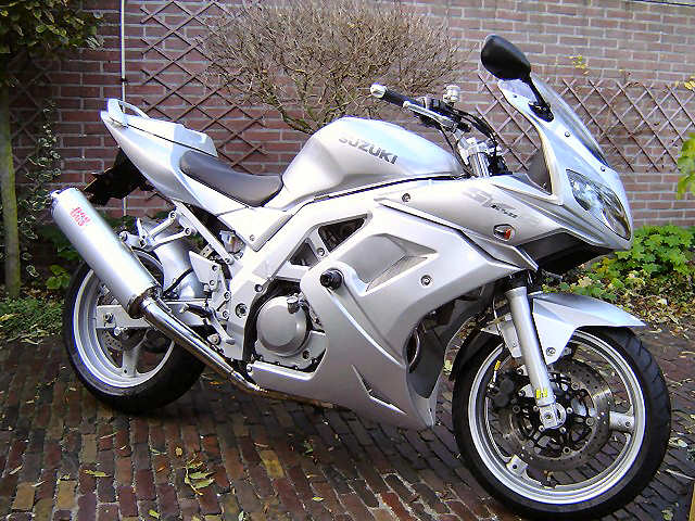
| What is the Suzuki SV? The SV650 was originally introduced in 1999. It was available in two versions, faired (SV650s) and naked (SV650). Production has continued until 2002. In 2003 the SV650 and 650s were updated with new styling and had fuel injection added. The engine may be interchangable between the old and new models but not much else is. To complement the SV650, Suzuki also introduced the SV1000 again in naked and faired versions. |
| What are the specifications? See my link to the specs on the Stratten site. |
| What are the performance figures? Figures are pretty thin on the ground at the moment (Nov '99) but these figures were published in May 1999 Cycle World : 1/4 mi. 11.85 sec. @ 110.17mph. |
| Are
there issues with cam chain tensioners?
Yes, on some bikes the cam chain tensioner(s) are very noisy. Get them checked by your dealer. Instist on having them replaced under warranty if you are still concerned that there is a problem. I had my cam chain tensioners replaced under warranty on 06/11/00. |
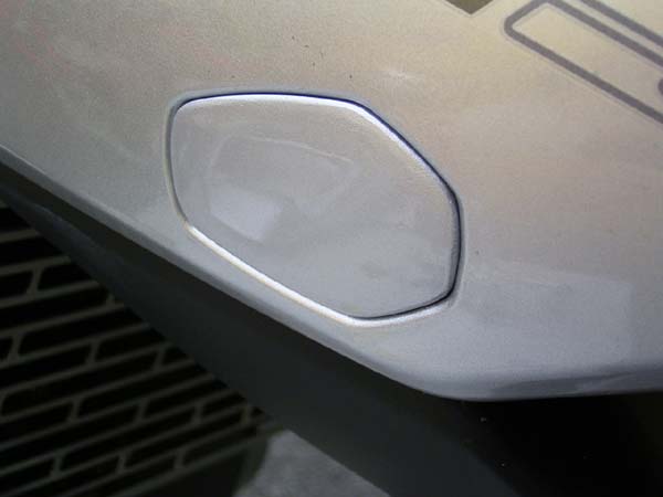
| Are
there issues with fuel filler caps?
Yes, in some cases water can collect in the fuel filler cap recess in the fuel tank and will not drain away down the drain tube because the tube may be kinked underneath the hinged fuel tank. See deal with water in the fuel for more information. See also this word doc from Steve Warburton. |
| 27/11/00
- HOWTO - UNSEIZE
THE FRONT BRAKE CALLIPERS - Ian ian@netgates.co.uk
once again supplies 'how to' information...thanks for your effort
Ian!!
N.B. Read all of this before you start. If you've not got the right
tools or if you're not confident in using a tool kit, then get a professional to do it. it involves the braking system, and you don't
want to get it wrong. |
| 02/01/01
- How to - The lazy way of front fork adjustment -
Jerry Lynjed@aol.com
has it sorted...if you follow this let me know how it goes...
Here's a piece for your FAQ section. Oh....OK then.... My reworking of the SV continues - just thought I would send the lazy way of changing the fork oil and adding spacers - without removing the forks! Lets face it, removing the front wheel, mudguard, calipers, forks etc is a right pain - there is a better way and it can be done in under 15 minutes! You need a thin bamboo pole about 3 foot long, 2 metres of 10mm flexible pipe, a bent nail, 1 litre of fork oil and a selection of 35mm washers. You are now ready to convert the washed out front suspension without removing the fork legs and it can be done in under 15 minutes! First loosen the fork caps, now jack up the front wheel clear of the ground. Some people prefer thicker 20 sw oil, or more spacers, around 19mm not uncommon. With the rear set on number four, the front now feels matched, doesn't flop when braking and has helped no end with the pitching (UK roads). Rates about a seven on the improvement scale. You could do better and fit aftermarket springs but not for the �8 the above cost inc the oil. So there you have it - the laziest way of uprating the SV front yet! Kev, haven't forgotten about rewriting the undertray bit - waiting for a sunny day for nice piccys etc. Thanks, send them when you have them! My next job is the rejetting for the Scorpion can ( bloody loud can or what! - has transformed lower pulling power though) - there must be a lazier way for that! If there is you'll find it.... |
| 23/01/01
- You can now get an SV manual - thanks very much for this info James weazel2001@go.com
....
I enjoy your site and have found it very useful. good... I recently ordered a repair manual from Motocom, the url is http://www.motocom.com It is the official Suzuki service manual for both the sv650x and sv650s. It comes unbound in loose leaf form and is punched to fit a standard 3 ring binder. It is not as user-friendly as a Haynes or Clymer manual, but contains every technical detail. Or you can download from this site here |
| 08/02/01 - How to install a Targa Fairing - thanks very much for this info Frank palocsay@shentel.net |
| 13/02/01
- Heated Grips, a How To - Thanks very much Frank palocsay@shentel.net
View the how to |
| 28/02/01
-
Additional instructions on installing
Scottoiler kit - many thanks go to
Jonathon jm@checkerbox.com
Kevin, thanks for an outstanding site. thanks.. Here are some additional
details on installing a non-touring ScottOiler on a California-model bike. (I
know you're in the UK, but we're readin' you all over the world!) |
| 28/02/01
- Undertray
fitting instructions - Thanks to Jed Lynjed@aol.com
for supplying this information...
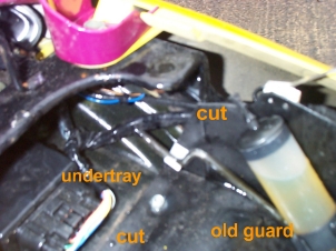
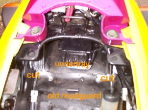
As promised ages ago here are the revised details for undertray fitting that does away with dodgy tie straps and the like as details in the FAQ. No doubt undertrays differ, but most will be similar. Most of the weight of the fender is removed but the remaining allows a firm installation of the tray. First remove both seats, then the rear bodywork. There are four bolts
under the seats for this, plus two screws underneath. Beware also that there
is a locating lug at each side that the panels push into - carefull pulling
pressure is required. Split the rear bodywork (the cable for the seat lock
is easily removed) by removing the two screws holding the rear light cowl,
and also the rubber washers were it fastened under the seat. It is easier to
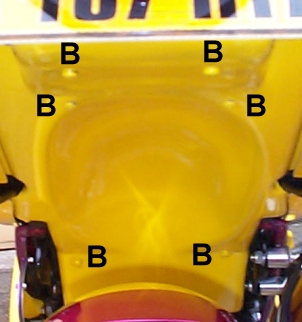
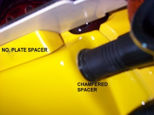
fit the undertray whilst wresting with one side of bodywork at a time. Your undertray will now fit badly around the rear light! The undertray emerges at the light from underneath the rear body and swaps to being on top at the last 15mm. This allows you to screw through this into the existing lugs right at the rear of the bodywork. By careful filing you will slowly get an improvement. Again I had to use a ciggy lighter, to warm the undertray, and bend the edges for a better fit. The gap looks worse than it is - you will know what I mean when you fit it! Put the light cowl back on top and the rear seat to cut out the light and things will look much better. I spent over half the time fitting mine (about 3 hours) shaping around the rear light. At the other end your undertray will locate over the battery box (mine was short and so I positioned the tray biased for the rear light, so the flange that locates under the battery box is 5mm short but this does not matter. When your happy drill through the battery box just to the side of the battery connection symbols, through the undertray and pass two bolts through (bottom B on image BOLTS1). Slowly tighten these and they will pull the undertray tight up to the rear fender - you may need 1" long bolts and cut them off after you have tightened them up. Replace the battery. At the other end, drill at the end of the fender where you cut it off and pass another two bolts through and tighten up (middle B on image BOLTS1). Locate the circuit box from the original fender and relocate right at the back of the undertray drilling through from underneath, using two more bolts (top B on image BOLTS1). Fit the indicators - I would recommend aftermarket flush mounted ones as the originals will point downwards and backwards due to the angle of the undertray where they relocate. I used the originals by making two plastic spacers/washers beveled from 5mm to 1mm across the width, rotating these I could re- align the indicators straight (see image INDICATE1). Finally drill the undertray right at the rear after bolting on the rear bodywork to pick up the two existing lugs - carefully! Fit the final two screws. I drilled the underneath of my rear light and filled the holes with clear glue. I then made a spacer that both angles the no. plate and brought it forward by 25mm- see image INDICATE1. The idea was to illuminate the plate from the rear light as you are now minus the little light that was in the old fender. It half works! To finish it off I made a plate that has two sticky reflectors either side of the no plate ( any old car spare shop sells these) and fastened it on before the plate - this keeps it legal. You now have a sexy rear end! - See image REAREND. Incidentally my undertray was color painted, and I managed to fit it without a scratch - Its that easy if you are patient. My bike also has a rear hugger fitted and this does not interfere with the undertray even though you have put it on top of the old fender. rearend.jpg cut1.jpg cut2.jpg indicate1.jpg bolts1.jpg I have posted this to the FAQ section.... |
|
04/04/01 Replacement keys - Much thanks to Tony TonyP2020@aol.com for this information There is now a Silca (make) key blank available for the Sv650. The number is SZ14RAP. Any shop which cuts key should be able to get hold of it. |
|
|
|
27/06/02
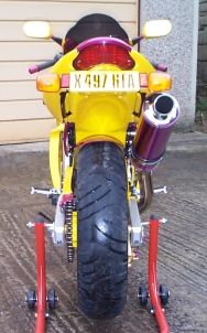
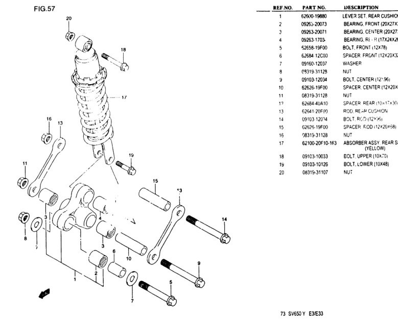
How to fit longer dog bones to lower the suspension from Mark
Glasswell
In the attachment the links are item 13. Before you start place something soft in between the back wheel and underside of bike I used a couple of old cushions and get hold of an assistant (I used my eldest lad!) Tools are 14mm and 17mm(?) sockets, spanners, extension bar for socket and ratchet and a small hammer to tap gentle on end of bolts if persuasion required and a big hammer if everything goes wrong!!!!!!!!!!!!!! Undo the bolts and nuts (items 14,9,11,16. 17mm and 14mm I think) these are Tight and do require a bit of effort. the nuts are self locking. Remove link from the left side. Get your assistant to LIFT the back end by the grab rail as this relieves the pressure on the link and the bolts will just gentle ease out. Remove other link and bolt fit new link by lining up holes by getting your assistant to lower the bike back end (this is why you have the cushions just in case it slips!) Once first link is on and bolts in place assistant gets the sack surplus to requirements fit other link and nuts and retighten and there you go 20 minutes tops! Hope it helps. Image Links provided by James Holland Racing www.jhsracing.com Work is carried out at your own discretion and that SV650.org accepts no responsibility for any modification carried out. |
| Parts Fiche available here and here |
|
|
| The correct pressures for Avon Av35/36 tyres are 36psi front and 42psi rear. |
|
|
| What
is the paint code for my bike Compiled by Stu Kennedy
Hi John I like many others have asked for information on paint codes. I've tracked down what I believe are all the colours and year they were introduced. It may be worth adding this list to the FAQ's section to aid riders get the right hugger or belly pan. Regards Stu.
|
|
|
| SV650
Suspension FAQ
Is the GSXR 750 front end a straight bolt in? From what yrs? Pre-SRAD gsxr stuff goes right on, only requires changing the steering stem bearings from ball to roller. EZ. The hot racing setup: get a 98-99 GSXR600 front end. Its fully adjustable and as light as they get. Its also (arguably) too short, requires a custom upper triple clamp that allows the forks tubes to sit lower than they normally would. You'll also need to press in the SV (or pre-SRAD gsxr) steering stem into SRAD lower triple clamp. Add gold valves and it doesn't get any better than this. The downside is cost, its the most expensive front end out there, the wheels are expensive, and the upper triple will set you back a couple of bucks as well. For pre-SRAD stuff, get a 93?-94? GSXR 1100 front end (kayaba forks). These are the longest gsxr forks out there, allowing the most adjustability. The 750 Showa forks work too, but are 15(?)mm shorter. If I did it over again I woulda held out for a 1100 front end, more ride height adjustability. Does this require changing the rear shock as well to maintain balance between the front/ rear? Yes. If you stiffen up the front end w/o increasing the rear ride height you will find that the bike has way too much weight on the back of it. As you get moving quickly (100? mph or so...) the bike will start wobbling, then headshaking. Bad. Very bad. When I bought my bike it was stock, it was friday pm, and I was racing the next day. Added preload to the front forks to get the proper sag. It wobbled BAD. Dropped the front ride height, and it still wobbled. Played around in EVERY morning session (pissed off race control..) trying to get the bike to work, then I gave up and put it back to stock preload and ride height and it stopped wobbling. Is there a tangible gain for the average street rider? No. If my SV were a street bike I'd put emulators (and springs) in the forks and a GSXR shock on the back. For about $400 you'd have a top notch suspension setup. The emulators are outstanding, I raced them for 3 years on my hawk and highly recommend them. They provide 90-95% of the benefit of a cartridge+gold valved front end, and I honestly believe they work better than a non-gold valved cartridge fork. Nope, I'm not sponsored by race-tech, I just think their products are outstanding... -Mitch in MI Maximum Overdrive Racing: http://www.reish.net/maximumoverdriveracing Sharkskinz / Street-n-Comp / M4 / Reish.Net / Service Honda |
|
|
| How
to make a fender eliminator for the '03 SV
by Mitch
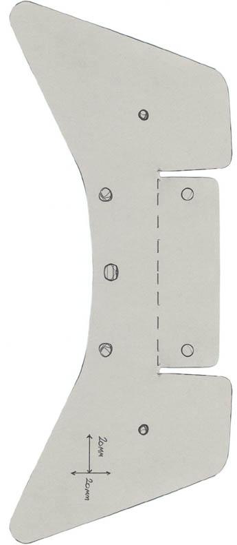
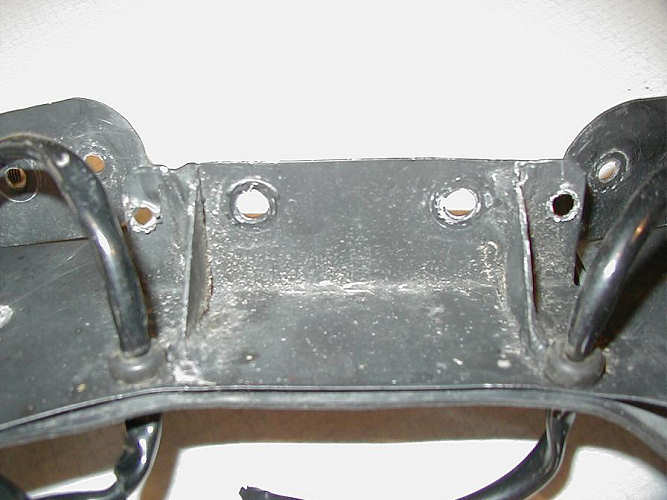
I did a "Do It Yourself" jobbie to remove the hideous hunk a crap on the back. First, you need some tin/stainless steel to make a metal template. 1. Print off the template and make sure it
is to scale. By measuring the 20 mm by 20 mm.
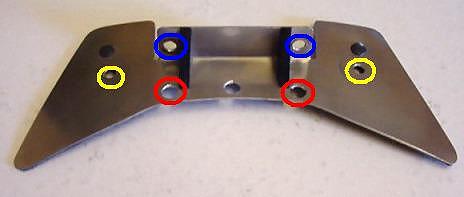
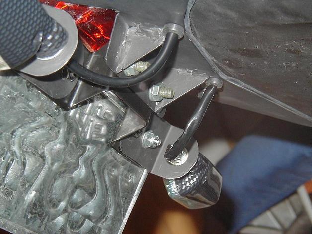
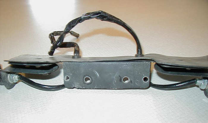
2. Bend the metal according to the next picture. Also, drill the four holes. NOTE: The center hole is not needed. RED These holes were used to bring the indicator wire into the "trunk" and connect were the stock wires connected. BLUE These holes are used to mount the license plate and Rsend. YELLOW These holes are used to mount the homemade undertail to cover the gap left behind by the rear fender. This template is made to fit directly where the old fender fit.
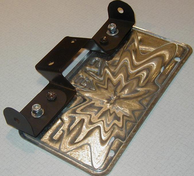
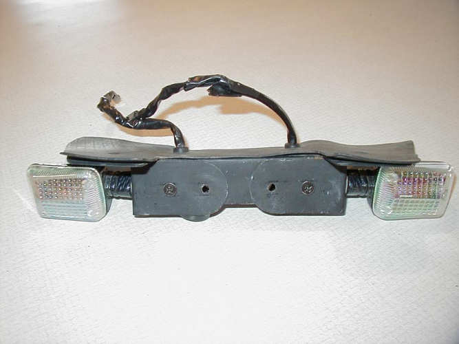
3. I used the stock license plate holder. Them made two "Ears" to hold my aftermarket indicators. The Ears were made out of the same material for the undertail.
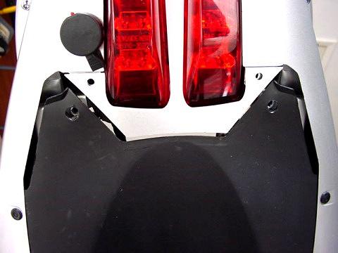
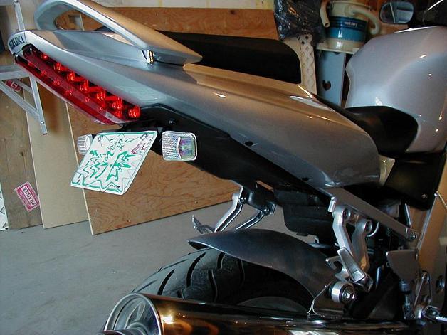
4. Step four... basically mount everything. Put the plastics back on... I forget the exact order. You took it apart, you can remember. Should look something like this:
As you can see, I cut a tire tube (just bigger than the template) to put between the undertail and the tail so give more of a "cushion" and prevent moisture getting into the "trunk". Also, I put heat shink tube to seal the wires. Also used rubber grommets to prevent the wire from rubbing and wearing away on the metal. And the finished product...
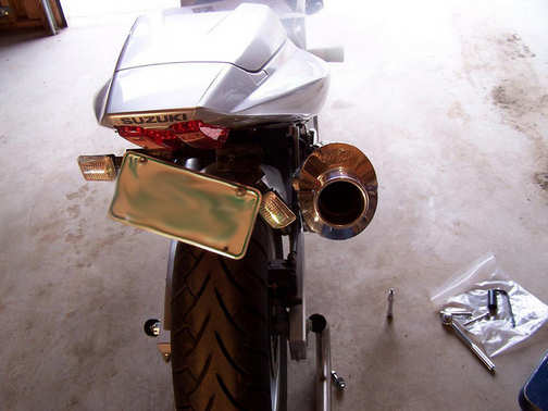
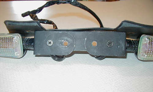
Thanks, Mitch Updated 11/04/2005 Hey, This is a modified version of the How to make a fender eliminator for the '03 SV by Mitch. The reason I decided to do this modification is because my M4 high-mount exhaust interfered with my right signal light. The light would not fit between my license plate and the canister.
Instead of mounting the ears on the Rsend, I decided to mount them on the template. Another hole needed to be drilled in the template for the ears. This is so that the ears have two bolts holding them on so they cannot pivot. An awl was used to make the holes big enough for the bolts.
The ears were then mounted onto the template with the outer holes.
The inner holes on the template and ears were widened with an awl to make the stock Suzuki bolts from the Rsend fit.
The Suzuki Rsend was then mounted onto the template atop the ears.
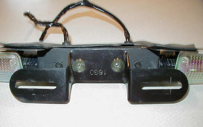
Mount your license plate onto the Rsend and you are complete.
What this modification ultimately does is move the indicators behind the license plate so they can be moved inwards and away from your high-mount canister. The only downfalls that I can see are the indicators are slightly covered by the license plate. Also, they are tucked quite close to the tail and may not be as visible as before. Another issue, the right indicator is hidden by your canister from the rear right. Something you can do to solve this problem, which I am doing, is buy the Clear Alternative�s integrated tail light. Thanks, Mitch |
|
|
|
Fitting
an adjustable clutch lever to the
SV650 by Paul Baxendale What you
need
Part No.: 46076A lever_assy_grip,clutch Blanking plug Part No.: 92066 Plug (or get a bag of assorted blanking grommets from any motor factors) Tools Cross head screwdriver, Socket set How to do it
|
|
|
|
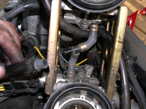
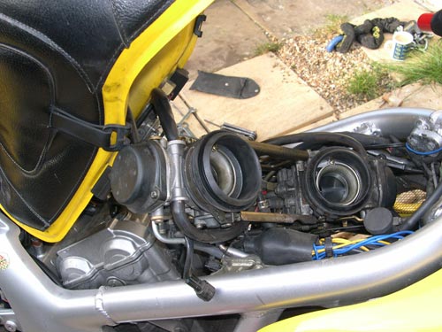
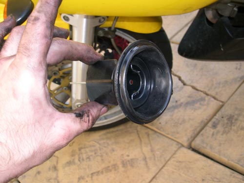
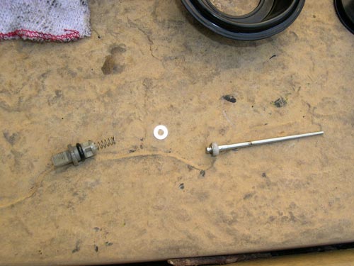
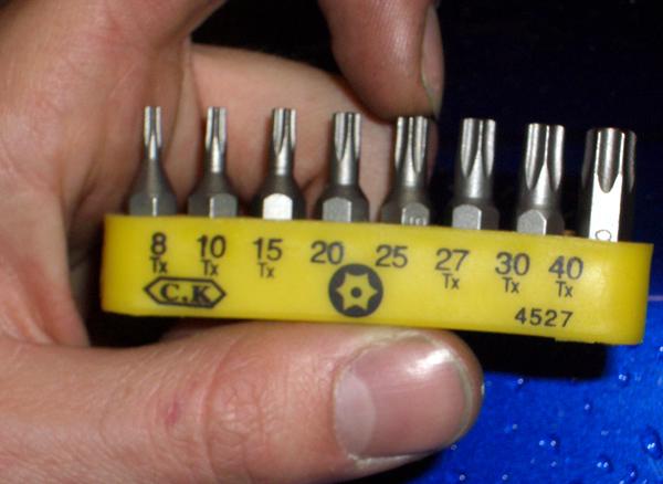
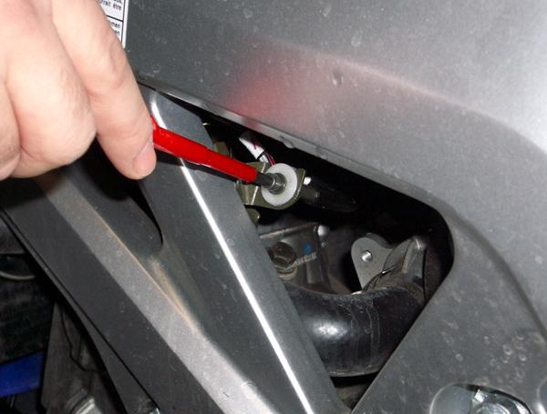
Adjusting the Throttle Position Sensor (TPS) on a 2003 - SV Step-By�Step� Guide **Before undertaking this modification, I strongly recommend that you read the instructions through from start to finish & have them to hand during the process** You will need: A length of fairly thin wire (multi-core like the stuff you get on the end of cheap jap speakers is what I found worked best) A Size 25 Security Torx bit (part no 285-9488 from RSwww.com) photo 1:� You will need to make your �dealer mode tool�� Simply take a piece of wire about 3 inches long and strip back about 8mm of the insulating sheath (twist the cores together on multi-core cable).� Snip off the last 2-3mm with a pair of scissors or a wire cutter to leave a clean end. 2:� Undo the side panels under the saddle�And remove the saddle� 3:� Undo the tank retaining bolts�and prop up the tank 4:� Run the engine until at it�s normal operating temperature (most are around 85-90 degrees � I plump for 86!!) 5:� Check & adjust your idle speed�� It should be about 1200rpm. 6:� If (as above) the
idle is too low, locate the idle adjust screw � on the left hand side of the
bike in one of the triangle shapes in the chassis and adjust.� Turn clockwise to raise the idle speed and
anti-clockwise to lower it�� Go in small movements and �blip� the throttle after each adjustment and allow
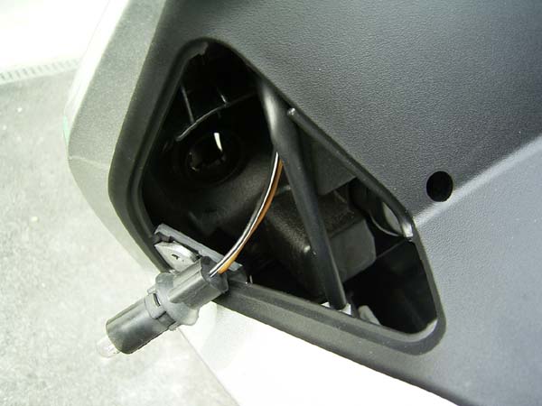
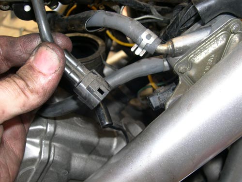
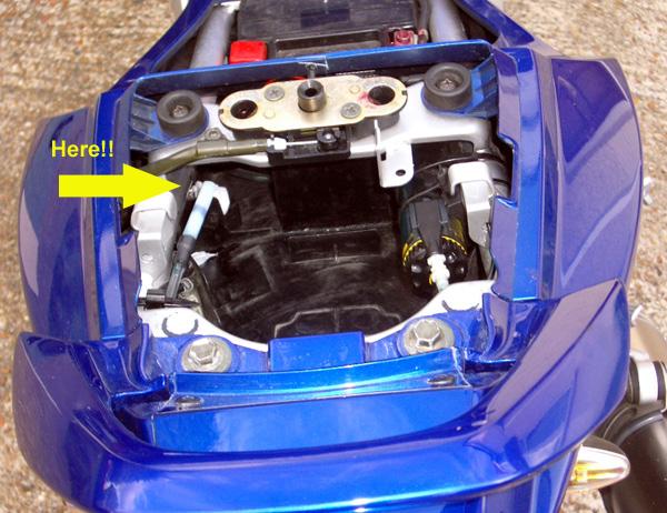
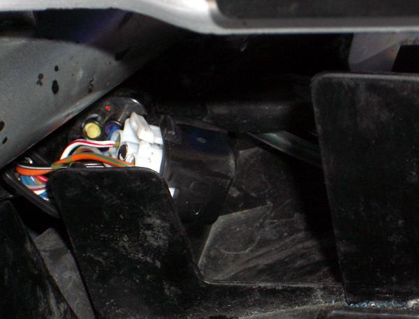
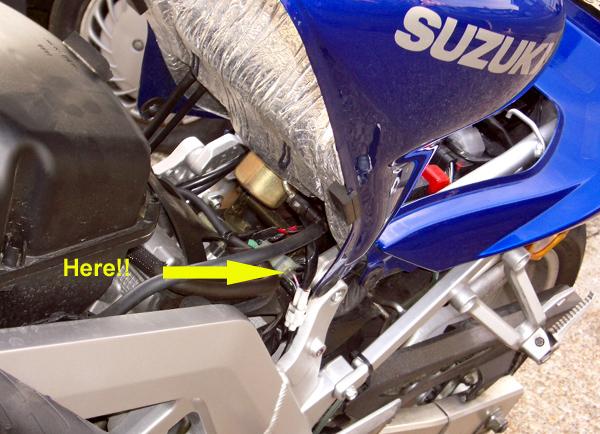
it to settle before trusting what the rev counter says! photo 7:� Undo & remove the pillion seat. 8:� Locate the Dealer Mode Activation Connector If you look into the tail unit from behind, on the left hand side you should see a bunch of a few wires & connectors behind a bit of plastic protruding from the undertray. Follow this bit of plastic down towards the rider�s saddle
and you should find another connector.� It�s rectangular, white plastic with 6 holes for connectors in and only
4 of them used.� It also has a black
rubberised cover on it. photo
photo
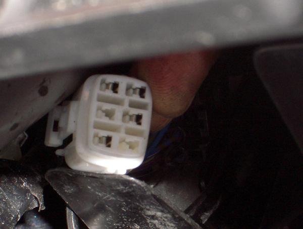
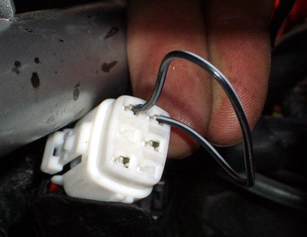
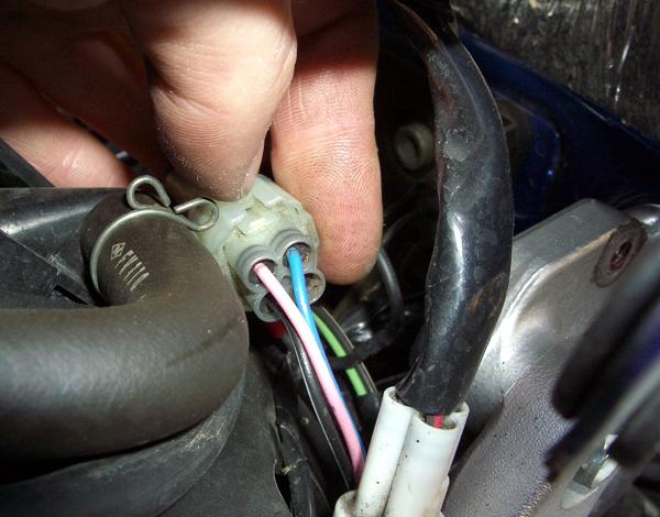
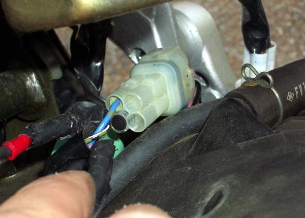
photo 9:� Turn off your ignition and put your �dealer mode tool� in the two terminals that are next to each other. ]**WARNING** Do NOT short out the wire onto the chassis or any other part
of the bike.� Do NOT connect either of
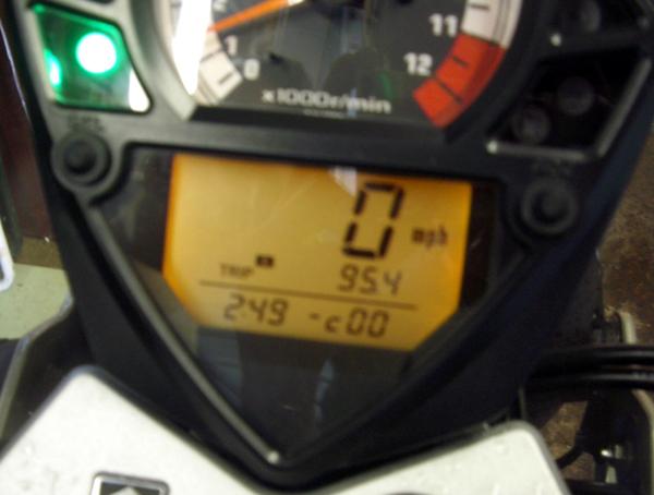
the other two terminals to anything photo 10:� With the �tool�
still in the connector turn on your ignition.� The temperature display should have disappeared and now you will see a
little line (like a minus sign), the letter c followed by two zeros.� If you have any other numbers shown in this
display, see http://www.tl1000.com/faq/fi_codes.htm
to diagnose
your bike�s fault (it�s the dealer diagnostic display!) photo 11:� SLOWLY turn your throttle while looking at the little line on the dash�� It should move from the middle of the zeros to the top at about 1450rpm.� I will bet money on the fact that it won�t!!� It will probably move at about 3000rpm. This is where the fuel injection starts injecting more fuel
into the engine so when it�s set too high the bike will be jerky at low
speeds!� (The line takes a second or two
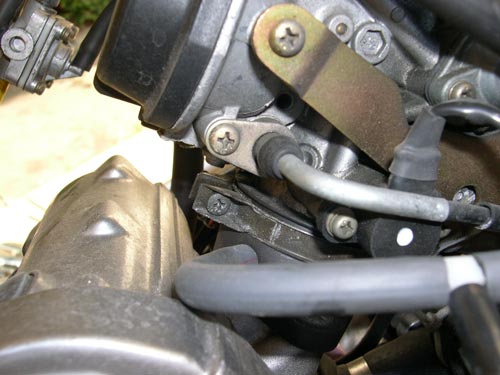
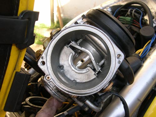
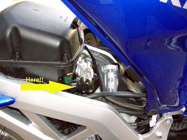
to move, hence turning the throttle slowly!) photo 12:� Turn off the
engine and locate the Throttle Position Sensor�� It�s under the tank on the left hand side of the bike, just
behind the air box. photo
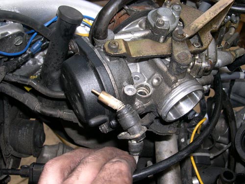
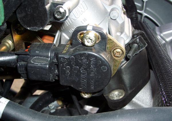
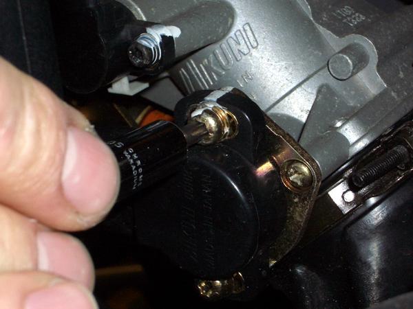
photo 13:� Using your size 25 Security Torx bit� CAREFULLY undo the two torx bolts on the sensor (the
ones at the top & bottom, not either side!). photo **WARNING** The bolts are very hard to get to (especially the lower one) and are made of a very fine, soft French cheese!!!! I found it easiest to adjust if you don�t undo the top bolt very much as this way you can pivot it a bit better! 14:� Start the engine and turn the sensor anti-clockwise (I think) to decrease the sensor�s activation point.� You will need to make very tiny movements of the sensor! You may find that the engine cuts out (or nearly cuts out).� If it does stop, try moving the sensor back in the opposite direction & thumbing the starter button again.� If this doesn�t help, try increasing your idle speed a little at a time until the engine starts & runs properly again! 15:� Keep making small adjustments, turning the throttle slowly while looking at the display to see when the line moves to the top of the display.� It should stay in the middle of the display whilst idle and move to the top at around 1450rpm. 16: Once you�ve got the line to move at about 1450rpm, very slowly tighten up the bolts on the sensor again � it�s easiest to do the top one first. It�s not a bad idea to hold the sensor steady as you tighten it, as if it moves, the sensor will activate at a different rpm! Check that the line moves at the same revs after you tighten each bolt. 17: Remove the �tool� from the connector, replace the rubber cover, tuck back where you got it from and check that the temperature display returns on the dash!! 18: Put the tank back down, replace your saddle, side panels and pillion seat and go and test!!! I accept no responsibility for this modification or any unexpected effects you may encounter. Tim Coombes 15/7/04
|
|
|
|
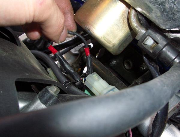
How to Modify the Timing Retard Eliminator (TRE) Modification on an SK3 and above SV Step-By�Step Guide You will need
1: Make your TRE resistor connector! First take the resistor, cut the ends down so it�s about an inch and a half long in total (too long & it will break under the tank!!). Take a length of the wire, about two inches long, strip back the sheath at one end and twist the cores together. Twist one end of the resistor onto the bare end of the wire and then solder. Repeat this for the other side of the resistor! Strip back the sheath at each end of what you have & crimp on one of the Miniature female spade connectors. Take the heatshrink sleeving and cut it to length so that it covers the resistor and most of the cable (not the bare wire though!!) � Heat to shrink!! Fit another spade connector to the remaining bare wire. 2: Undo the side panels under the saddle�And remove the saddle� 3: Undo the tank retaining bolts�Lift the tank & prop up with the tank prop (surprisingly!!) 4: Locate the 4-way connector (with only three wires in � blue, pink and black & white) that you will need to modify! photo For Step 5 you might find it easier if you give yourself a little slack on the wires by undoing the retaining wire pictured below�photo 5: You need to remove the pink and the black & white wires with their spade connector from inside the enclosure from the female (outer) side of the plastic enclosure � the wires have a male mini spade connector on them. They are held in place with a tiny metal lug that sticks out from the spade, use the tiny jewelers screwdriver to prise them out (It�s bloody awkward but it can be done, trust me! Just persevere with it & be careful not to bend or break the spade connector!) photo photo 6:Take the TRE resistor �bit� you have made & connect it to the bare ends of the two wires you have removed and tape round the naked metal with the electrical insulation tape. It should look like this� photo You can tidy the wires away nicely back where they came from, remembering to re-do the cable retaining wire you may have undone. 7: Turn on your ignition, look at the rev counter & pull in the clutch�If the mod has been successful the revs should rise when the clutch is pulled in! 8: Put the tank back down, replace your saddle and side panels and go and test!!! I accept no responsibility for this modification or any unexpected effects you may encounter. Please note: you may invalidate your warranty by undertaking this modification. Tim Coombes 15/7/04 |
|
|
|
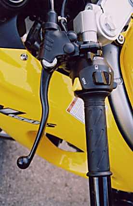
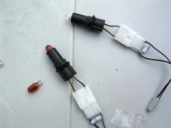
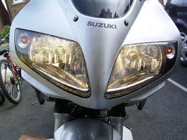
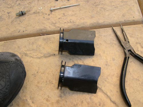
How to fit a ROCA indicator conversion kit to a 03 onward SV650s by Clive Goodwin As expected, the kit came without instructions, but I blagged my way through it... If I can do it, anyone can First of all, remove the little 'quarter panels' directly in front of each handle bar (one screw!) Remove each of the sidelights from its respective holder by rotating it a quarter turn.
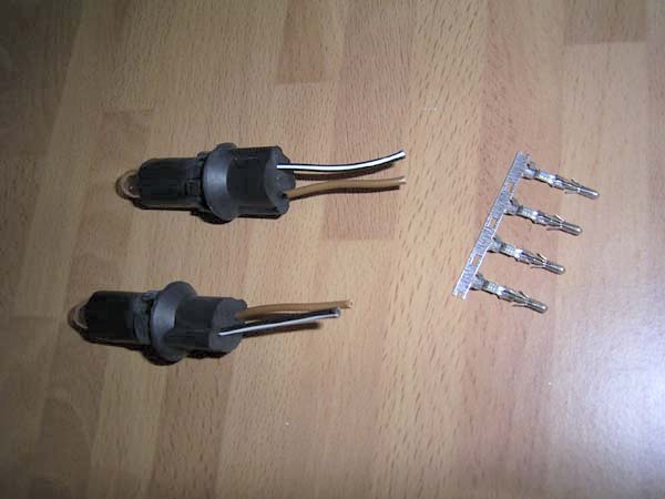
Cut off the sidelights, leaving yourself about 2" (5 cm) of wire to play with... Prepare the sidelights by removing approximately 1.5 cms of insulating sheath from each of the cables - also remove each of the connectors from the strip supplied
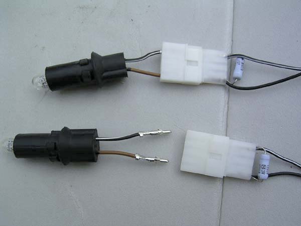
Fit the connectors to the cables using a crimping tool.. Then the prepared sidelight parts have to be connected to connector blocks - to do this, break apart the two halves of the connector block (see below) then push each of the four newly attached connectors into the female halves of the block, you will hear a click when they're in position...
When all the wires are connected, re-connect the male & female halves of the connector blocks..Then remove the 'white' bulbs & replace them with the orange bulbs (supplied with the pack)
Remove the original front 'cators (including the backing plates). Locate the indicator blanking blocks, washers & screws (supplied with the kit)
Fit the blanks into each of the holes
|
|
|
|
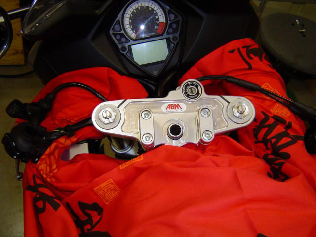
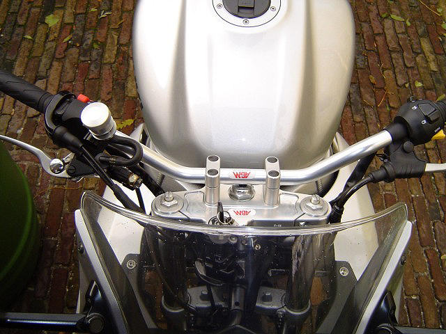
How to fit an ABM handlebar conversion onto a mark2 SV650S by
Jaap van Dijk
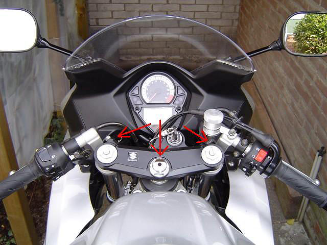
I bought a ABM handlebar conversion kit last October for my 2003 SV650S which I have recently mounted. I intend to share my experiences with you, with the help of some photo�s (of which some are a bit blurry...sorry). As I have a SV650S, some things will not be similar with the SV1000S, but I try to mention the differences in the steps below. People with the old model can also use this guide, but for example the rerouting of cables is different of course. On the old model the fairing also has to be modified. Note: I�m not responsible for any damage to your bike because of the use of the steps below. Use of this fitting guide is at your own risk! First part of the conversion is stripping the bike. First loosen the nuts on both ends of the upper triple tree (photo 1). As you can see in some of the other photo�s, I used a different working order which was not so smart. :)
Then loosen and remove the steering stem head nut (photo 1), beware of the washer underneath it. Keep the washer in a safe spot, because you will need it later. Carefully remove the triple tree. Now you arrive at a tricky part, because the ignition lock has to be removed from the triple tree. It�s mounted with two torx screws, with a little pin in the middle. Anti-theft stuff. You can a) buy a the right torx bit at a shop or b) remove the little pins out of the screws. You don�t need them again, except when you want to remount your stock triple tree, because new allen screws are part of the kit. At least, in my case with the ABM kit. When the screws are removed, the ignition lock can easily be removed. Ok, next step. First, put a cloth on your fairing to make sure you don�t damage or scratch it. The most wise thing to do, is to drain the brake and clutch system before you start removing the clip-ons. First remove the bar end weights and then loosen al the parts that are mounted on the clip-ons (so you can slide them of easily). The left-hand grip can be reused, just carefully loosen it with a screw driver or something like that (photo 2). Remember to disconnect the wires on the clutch and throttle switch box! Then loosen the clip-ons, take them of the fork legs and slide of the switch boxes, clutch and brake cylinder.
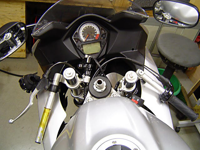
Now there are two things you can do. You can mount the new triple tree or you can reroute the wiring and cables. Most wise would be to do the rerouting first. The clutch cable on the SV1000S will have to be replaced with a new and longer one, but unfortunately I can�t help you on that one, because I don�t have a hydraulic clutch. The throttle cables can be reused, but will have to rerouted from the left part of the frame to the right part of the frame. See the tips at the end of my post for another solution. So it�s time to remove the side covers, riders seat, fuel tank and air box. For a detailed �How to topic� on removing the air box, I would like to refer to this topic on the SV1000 portalof BJAM and the Workshop manual. Before you remove the last air box part, put some clean cloth�s in the intake trumpets so no dirt can fall into it when removing the air box. You need to open the throttle unit and loosen the throttle cables, in order to redirect them. As you (hopefully) can see in photo 3, the cables or now running from the left side of the bike to the right side and come out of the right hole in the frame. The red arrow indicates the mounting point and the red line indicates the stock route of the throttle cables. The green arrow indicates the new route of the throttle cables. The throttle cables should run on the other side of the front fork leg, and not the side that photo 3 shows. Small mistake... Look carefully at the small manual that comes with the kit, how the other cables should run. When all the cables are rerouted, it�s time to begin the mounting stage of the new triple tree. First mount the ignition lock, with the spacers and allen screws from the kit, on the triple tree. Now use the washer from the kit and place it on the steering stem. If you forget this, you won�t be able to turn the front end!!! I experienced that myself... Now carefully mount the triple tree, it has a very tight fitting. You could use some grease to ease the fitting. When the triple tree is in place, take the original washer and steering stem head nut an remount them. Before tightning, check if the front end can be turned. Tighten the nut at 90-95 Nm. (photo 4)
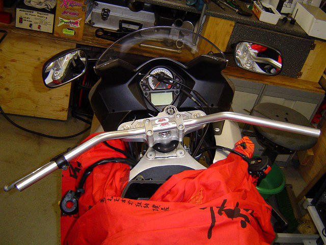
Next step is the mounting of the handlebar, using the two risers and four allen screws that come with the kit. Before you place the handlebar, slide the clutch assembly on the handlebar in case of a SV650S!! The rest of the controls can be mounted later. Make sure the handlebar can�t fall out and is in a position you think is right, tightening of the risers should be done later (photo 5).
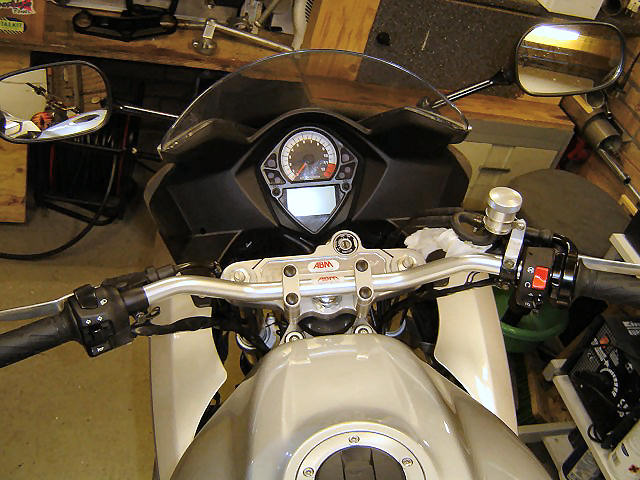
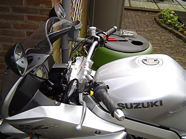
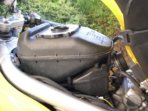
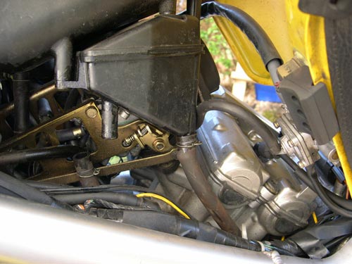
After the handlebar is in place, you can start remounting the brake cylinder, clutch switch box and throttle switch box again. It�s wise to already have mounted the new and longer clutch (on the SV1000S) and brake lines before you mount the brake and clutch assemblies. You can mount the brake fluid reservoir on the brake cylinder, by using the upper screw. I�ve made my own mounting bracket, but you can also bent the original bracket and use that. To mount both switch boxes, little holes have to be drilled in the handlebar to keep them in place. Make sure you drill these holes in such a way, that the controls end up how you want them to be. Use a cloth as shown in the photo�s to avoid scratches to the fairing from aluminum flakes. After the controls are in place, you can remount the throttle cables to the throttle unit and reassemble the unit again. The throttle unit has to be turned 90 degrees forward compared to the stock position when you are using the stock throttle cables. Important: tighten all the controls and make sure the throttle runs smooth again!! Remount the left-hand grip (photo 6).
Now it�s time to adjust the riding position. Turn the front end to the left and right as far as you can and make sure none of the controls touches the fuel tank. If everything has enough clearance (also check the throttle and clutch cables) and the handlebar is in a comfortable riding position for you, tighten the risers. Otherwise, readjust the handlebar. Reconnect the lead wires of the switch boxes and start the bike. Now again turn the front to the left and right as far as possible and check if the idle of the engine rises or drops when doing this. If not, everything should be ok. If it does, check where you could have made a mistake. Also check if the throttle responses smooth and returns to it�s starting position. Last thing that needs to be done is bleeding of the brakes and clutch. Again, I want to refer to a�how to topic� of the BJAM on the SV1000 portal as I can�t make it anymore clear then that. Another good link I ran into on this forum was this one. I�m sorry to say that I can�t say anything useful on bleeding the hydraulic clutch, but from what I�ve understood it�s the same as bleeding the brakes. So the links above should give you some help. Ok, everything is in place. Check if you tightened all parts correctly. You can use some tie-wraps to mount the electrical wires to the handlebar. If you do this, make sure the wires aren�t being damaged when the front end is turned. It didn�t work for me, because the wires or too short for that. Done! You can now take your bike for a test spin. Prepare yourself for an even worse view in the mirrors then before. Also a Racing (or touring if you like) windscreen can be mounted in order to redirect the airflow. Personally I didn�t experience turbulence, but the wind now directly flows on your throat, which sucks. Especially when the temperatures are dropping. The riding position is so much more relaxed!!! I intend to go on holiday with my bike in 2005, and with the clip-ons it wouldn�t have been possible for me. So I�m really happy with this kit. Total cost of my ABM kit (triple tree, handlebar and weights) was: 198,97 euro/ 258,25 US dollars/ �139.27 pounds including shipping. Some tips: - The small German manual says you can use the original throttle cables (and clutch cable in case of a SV650S), but it�s also possible to use the ones of a Naked model. Because they are longer, you will encounter less stress on the cables when the front end is turned and you don�t have to reroute the throttle cables. DO NOT BUY the Naked throttle cables because they will not fit . The SV650S/SV1000S uses a different switch box and different throttle cables then the Naked SV�s. I think ABM just took the manual for the old model SV, on which the N and S DO have the same switch box, and just replaced the photo�s. The throttle cables of a DL1000/DL650 are a alternative if you want longer throttle cables. I haven�t seen that in person, but they are pretty long. Perhaps even too long. - In case of a SV650S, consider replacing your clutch cable with the one of a Naked SV. I�m having trouble with the stock cable when the front end is fully turned left; it hits the fairing and the clutch play completely disappears. I bought the Naked cable and it has a shorter steel bend so it will not touch the triple tree and it�s longer so you can reroute it as the stock clutch cable. Do this switch when you�re rerouting the throttle cables, it saves you a lot of trouble. - Take your time when doing this conversion! If you want to do to fast you will make small mistakes, as I unfortunately also experienced in the beginning. - The workshop manual also contains a step-by-step manual for stripping the bike, so that can also be used when doing a handlebar conversion. When remounting other parts of the bike (brake hoses for example) use the torque settings mentioned in the manual. - For those of you who are thinking of buying such a kit, check eBay Germany for that. Search with the word �Gabelbr�cke� or �Superbikegabelbr�cke� and use �SV� to narrow your search. I�ll bet you will find a couple of sellers. The prices of a triple tree on eBay can vary from 140 to 175 euro�s, which are much lower then the UK/US prices that I have seen. Of course you�ll also need a handlebar (Lenker), bar end weights (Lenkerendst�cke) and longer SS brake lines (Stahlflex bremsleitungssatz), but most sellers also have that stuff. Hopefully you find this fitting guide useful as most of the kits come with German mounting instructions. If you have questions about this fitting guide, let me know. I�ll try to answer as good as possible.
Knaapie (the Netherlands)
|
|
|
|
First on the Scene Hi John, Seems a bit weird that this is the first email I’ve sent you, considering I’ve been knocking around on the forum for a while now… Following up on a thread in the forum where someone had come across an accident, I thought it might be useful to send you this handout which I was given when I attended a First Bike on Scene course with Lancashire Ambulance Service – perhaps you could upload it to the main site? It is only a summary of what is taught in greater detail on the course, but is informative nonetheless. The course is well worth attending as it gives a lot of information and teaches a lot of skills that may literally save someone’s life. I’m certainly glad I went, but thankful I haven’t yet had to use any of the things I learned. Hopefully see you at AR06! J Cheers, Andy (El Saxo) Not the sort of thing we want to think about too much, but sadly the dark side of biking. This kind of information is invaluable should you ever be involved in this situation. |
|
|
|
Fitting a ZX10 shock to a mk1
SV You need to cut the
battery box i found this to not only be the plastic part but also the
metal hinged part attached to the tank (but not part of the tank) -set the rebound damping to middle on the
shock and tinker with it as you ride to find what you like.
|
|
How to de-restrict a Mk1 SV
I am going to best explain how i have
de-restricted my bike which was fitted with a genuine Suzuki restriction
kit.
Thanks to Ricardo (TSM) for the 'How to' |
|
|
|
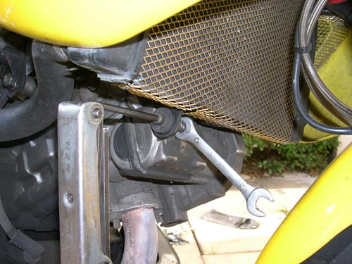
How to create a cheap radiator guard. By Derek Perry (25/10/2007) Total cost: about $4
Materials and tools required: - Aluminum mesh gutter
guard ($4 at Home Depot)
1. using a 4mm Allen wrench, remove the bolts holding the end brackets on either side.
2. measure and cut your wire mesh
gutter guard to the required length (about 18" in total,
3. take a few minutes to properly fit
and shape your new rad protector by hand.
4. once you've shaped it to fit
suitably, bolt one of the side brackets.
5. Once you've got both end brackets
bolted in place, the fit should be
|
|
|
|
How to check and adjust engine valves. This item does not reside on SV650.org but here is a link |


