Keeping her hands warm –
by Frank palocsay@shentel.net
The Germans (BMW)
and the Brits (Triumph) know that warm hands make happy riders. Both companies offer heated grips for their
bikes. Somehow Japanese manufacturers
haven’t yet discovered the cup holders of motrcycledom. As a BMW owner, I’m aware how much more
comfortable it is to ride in the winter when my hands are warm. For Christmas my wife got a new Suzuki SV650. She wanted a light bike to ride, both in town and on trips. She wasn’t ready for a bike as heavy as one
of the European sport-tourers, and she wanted a (nearly) naked bike, having
seen how expensive it is when a faired bike falls over. (Her learner bike fell against the BMW,
knocking it over into the lawnmower. No
damage to her 535 Virago.)
Wanting her to be
comfortable during our Virginia winter, I searched for aftermarket
cupholders..er, heated grips for her Suzuki.
I found two companies making replacement grips, Custom Heat Inc, http://www.customheat.com/main.shtml and Hot Grips, http://www.hotgrips.com/index.htm. Custom Heat makes very nice grips with
easily replaceable foam covers. However
these grips are styled to compliment cruisers, not sporty or naked bikes. Hot Grips are more traditional and much
closer to the Suzuki original grips. In
addition, Hot Grips offers an optional miniature switch and handlebar-mounted housing. In addition, Jim Hollander, Hot Grips owner,
will drill the grips for bikes with bar end weights. Finally, both companies include a 2 ohm resistor to give a “low”
heat range for the grips. The owners
of both companies were very helpful and the products were first rate.
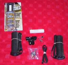
Here is the Hot
Grips parts. The large switch isn’t
used. Notice the little switch, sealed
cover and housing.
Installing the
grips is very straightforward. The
Suzuki grips are soft rubber and easily cut with a utility knife. Glue on the left bar can be removed with a
citrus cleaner. I roughed up the bar a
little with a file after cleaning off the old glue. The throttle grip is not glued.
It is easily split and removed.
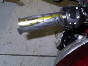
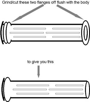
Before the heated
grip could be fitted I had to modify the throttle. There are three flanges molded into the throttle. The outer two flanges must be cut off before
the new grip will slide on. I cut off
the outermost flange with a utility knife and used a mototool with a cut-off
disk to remove the first inner flange.
I also cut off the two little ears on the innermost flange so the grip
would fit tight against the flange.
This is obvious when you look at your
throttle.
The instructions
that came with the heated grips suggest you should remove the ribs on the
throttle. Do not do this! I found the throttle grip fit perfectly over
the ribs.
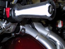
Once the old
grips are removed and the throttle modified, check the fit of the new
grips. I found the throttle fit
perfectly with no further work, but had to grind out the end of the left grip
before it would slid all the was onto the bar.
It is really important to fit the grips before proceeding as the
grips are mounted with epoxy. You
can’t easily modify the grips once you start to epoxy them to the
handlebars. Now mix up the epoxy. Since the grips get hot, chose an epoxy that
will not soften when it is heated.
Expecting the company would know which epoxy would work well I ordered
mine from Hotgrips. I applied a thin,
even layer of epoxy to the first three inches of the handlebar and throttle and
slipped the new grips on. Adjust the
throttle grip so the wire is at about the six o’clock position (straight
down). The grips have groves molded on
the inside. The epoxy is forced into
these grooves and locks the grip to the bar or throttle. By only putting the epoxy on the first three
inches very little excess epoxy had to be wiped off the bar. I let the epoxy cure overnight.
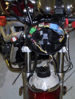
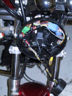
The next day I
wired the grips and switch. The
directions warn you to use a switched + 12 volt source to keep from running the
battery down if you forget to turn off the grips. This is very easy on the SV650.
There is an unused plug in the headlight housing. The brown wire is ground and the black/white
wire is 12 volts when the ignition switch is on. I cut off the plug and soldered a fuseholder to the plus 12 volt
black/white wire. I prefer the new
spade lug fuses, so chose a holder for this kind of fuse.
I decided to make
all connections inside the headlight housing so I ran the pairs of wires from
the grips, three wires from the switch and two wires from the resistor into the
back of the headlight housing. I
attached the resistor to the inside of the left headlight mount with silicon
rubber (don’t use epoxy. Apparently the
vibration and different expansion rates pop the resistor right off the aluminum
bracket. Ask me how I know this!) The wires are tie-wrapped to the existing
wires. Make sure you leave a three inch
radius loop of wire at the throttle.
Hotgrips claims the wire will flex many thousands of times without
breaking if you don’t bend it too sharply, thus the loop.
One thing I did
find. The switch contacts are not
mechanically robust. Do not try and
bend the wire once it is soldered to the switch! Jim Hollander was kind enough to send me a second switch. He also soldered a set of wires to it for
me. I had the honor to be the first person to break a switch contact! The best way, as explained on the Hot Grips
web site, is to strip 1/8” of 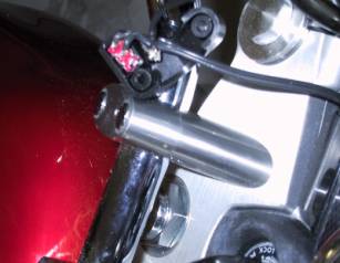 insulation from each wire. Tin the wires with a little solder and bend
the end to give an “L” with about 1/16” on each leg. Fit the wire into the switch contact, adjust so that the wires
will fit in the housing and solder with a small iron. Excess wire can be trimmed easily with small side cutters, or
better, cut off excess before soldering.
If you solder with the switch in the housing be careful, the
insulation from each wire. Tin the wires with a little solder and bend
the end to give an “L” with about 1/16” on each leg. Fit the wire into the switch contact, adjust so that the wires
will fit in the housing and solder with a small iron. Excess wire can be trimmed easily with small side cutters, or
better, cut off excess before soldering.
If you solder with the switch in the housing be careful, the
housing will
melt.
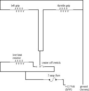 Here is the wiring diagram I used. Remember, I ran all wires, 2 sets from the
grips, three from the switch and two from the resistor, into the headlight
housing. I used nylon cable ties and
the existing wire guides to keep everything neat.
Here is the wiring diagram I used. Remember, I ran all wires, 2 sets from the
grips, three from the switch and two from the resistor, into the headlight
housing. I used nylon cable ties and
the existing wire guides to keep everything neat.
One wire from
each grip was soldered to the ground (brown) wire. The other grip wires were soldered to the wire connected to the
middle contact of the switch. One side
of the switch and a wire from the 2 ohm resistor were soldered to the
fuseholder. Finally I soldered the wire
from the third switch contact to the second resistor wire.. I used heatshrink tubing from Radio Shack to
insulate all connections.
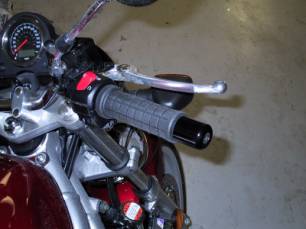
The finished installation looks
“factory.” Now my wife’s hands are warm
even when the temperature is below freezing.
Most of the time she can wear midweight gloves which give her much
better control of the bike. She is
appropriately grateful. Contrary to the
popular saying, it’s warm hands that make for a warm heart!